- Joseph Bushagour
The objective was simple in concept: trigger a servo motor to rotate a specific amount when an object passes the ultrasonic sensor at a specific distance. An idea easily achieved with almost any microcontroller around (provided it has 3 usable pins and at least 1 timer). However, the easy way is no fun. So I set a challenge for myself, could I do it without any programmable components, or more specifically, using only the venerable 555 timer? The answer is yes! Although, I did need 4 555 timers, 3 transistors and a plethora of passive components.The 555 Timer
The 555 timer is ancient, first developed in 1972 by Signetics (Signetics would turn out to be a "one hit wonder" of sorts in the IC development industry, with no later release even getting close to fame that would follow the 555) and still being produced to this day. It acts as a sort of swiss-army knife for electrical engineers, finding use in timer, flip-flop, pulse generation, time delay, and oscillation applications.
Its working principle can be generally understood by looking at the function of each pin.
Vcc- This pin is connected to a voltage between 5V and 15V.
Ground- I'm sure you can figure out what this pin is connect to.
Trigger- If a voltage beneath 1/3 of Vcc is applied to the pin, the ouput pin will be set high and stay high until reset with the Threshold pin or Reset pin.
Output- The output pin can be set either high or low. When high, the voltage at the pin will be (Vcc - 1.7V). When low, the voltage will be almost 0V at the pin.
Reset- When pulled low, this pin will manually set the output pin to low.
Threshold- In some configurations of the timer, there will be a timing capacitor whose voltage is monitored by this pin. When the voltage on this pin exceeds 2/3 of Vcc, the output pin will be set low.
Discharge- This is the pin in which the timing capacitor is discharged through.
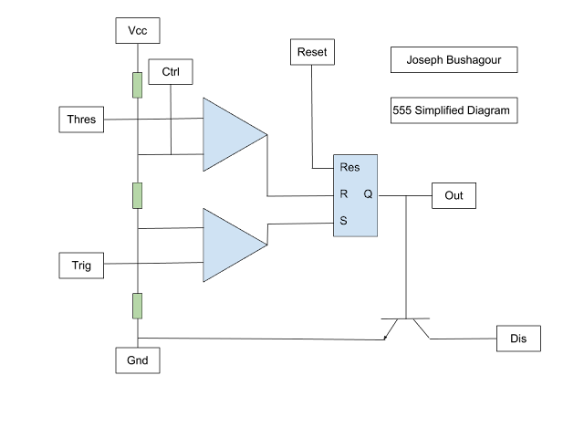
Control- Rarely used (when unused it should be connected with a 10nf capacitor to ground), this pin provides direct access to the internal voltage divider of the timer (as shown in the simplified diagram below).
It's also useful to quickly go over two common configurations of the timer that are used in the project.
Astable mode- The output does not stay high or low, rather it oscillates in a square wave determined by some passive surrounding components.
Monostable mode- In this mode, when a pulse of 0V is applied to the trigger pin, the output pin will be set high for a specific amount of time, then fall back low.
The Circuit
So how does the circuit work? How about we break it into what each 555 timer does.
555 Timer #1
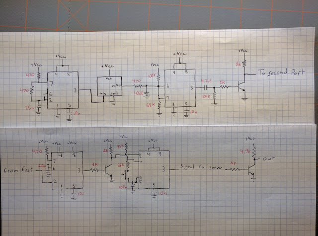
This timer is configured in an astable mode, generating an approximately 40 kilohertz square wave that drives the trigger pin of our HC SR04 ultrasonic module. The module returns a pwm signal from the echo pin, the duty cycle increasing when the module is blocked (the closer the blockage, the higher the duty cycle). This pwm signal is then averaged into an analog voltage by a capacitor, which then feeds that into the second timer.
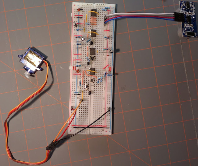
Here's a final picture of the result, hopefully now you can piece together what each part is doing.
555 Timer #2
This timer is used as more of a hack than a normal use of the timer. It's not configured in an astable, monostable, or even bistable configuration. Instead, I'm using it as sort of "comparator", with it's trip point set by a voltage divider. When the HC SR04 is sufficiently blocked and the analog voltage fed into the second timer is high enough, the output pin of the timer with go high. This high pulse is immediately differentiated by the following RC circuit, turning the constantly high output into simple a voltage spike. This spike is then inverted from being positive (normally 0V, higher during spike) to negative (normally 5V, lower during spike) by a transistor inverter.555 Timer #3
This timer is configured in the monostable mode. When the quick negative spike is applied to the trigger pin, the timer's output will go high for much less than a second. This output is inverted to being low, which is used turn on the final 555 timer for an exact amount of time.555 Timer #4
The negative pulse is connected to the ground pin of the timer, when the pulse is applied, the 4th timer is able to turn on. When this timer turns on, it is in an astable configuration, generating a square wave with a frequency of about 85 hertz. This is then used to drive the servo through a transistor (as the servo can draw much more current than the 555 is able to source). After the negative pulse on the ground pin is finished, the timer turns off.That's it!
While the circuit really isn't practical, as it would be ten times easier to use a microcontroller rather than the 555 timers, it makes up for that fact by being really interesting! Often I find designing systems with self-inflicted handicaps like this really help me view similar problems in a creative light and betters my electrical critical thinking skills. In fact, if you have a few 555s laying around, I'd recommend trying to make some challenging circuits with them yourself!Here's a final picture of the result, hopefully now you can piece together what each part is doing.


