-Joseph Bushagour
"Far out in the uncharted backwaters of the unfashionable end of the western spiral arm of the Galaxy lies a small unregarded yellow sun. Orbiting this at a distance of roughly ninety-two million miles is an utterly insignificant little blue green planet whose ape-descended life forms are so amazingly primitive that they still think digital watches are a pretty neat idea.” -Douglas Adams, The Hitchhiker's Guide to the Galaxy
As Douglas Adams explained in The Hitchhiker's Guide to the Galaxy, digital watches are "pretty neat" to us primitive life forms. Something about the marriage of practicality, and sheer nerdiness gets me oddly excited. Somewhere in my fascination I asked myself, "can I make a digital watch entirely of my design?" I did! And it taught me a lot about pcb fabrication, low power programming, and shift registers.
As Douglas Adams explained in The Hitchhiker's Guide to the Galaxy, digital watches are "pretty neat" to us primitive life forms. Something about the marriage of practicality, and sheer nerdiness gets me oddly excited. Somewhere in my fascination I asked myself, "can I make a digital watch entirely of my design?" I did! And it taught me a lot about pcb fabrication, low power programming, and shift registers.


((For a higher resolution video, check here))
DS3231, the Timekeeper
Probably the most important function of a watch is that it keeps time. While you could use your microcontroller to count the seconds and save on parts, there are some major downsides to this. For one, the microcontroller is much worse at keeping time than a dedicated RTC (Real Time Clock) IC, the time would drift significantly with temperature and battery voltage. Another serious problem is that it would require the microcontroller to always be on, keeping track of the time. This would consume much more current than an RTC IC, draining the battery significantly faster. Thus we employ a DS3231 to casually sit in the background, consuming microamps from it's own back-up battery (which, at the rate of 200µA, would take 12.56 years to drain).
ATtiny85, the Brains of the Operation
First released in 2005, the ATtiny85 is more recent than its larger cousin the ATmega328, (known from Arduino fame) which sits at an aged 1990s vintage. Still, the IC is easily found in the somewhat antiquated DIP package (dual in-line package) ((the term DIP package has a slight case of RAS syndrome)). Ignoring the pleonasm, the DIP package is extremely easy to fit on a breadboard, making it wonderful for prototyping, and a little big for production.
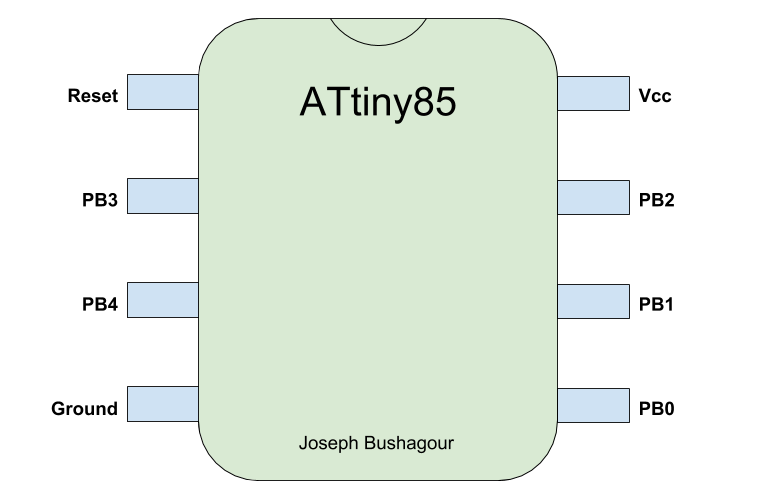
The ATtiny is programmed very simply for this project. The tactile switch that initiates the time display process is simply connected between the reset pin and ground. When it is pressed, the IC will restart and execute the following steps. First it uses pins PB2 and PB0 to communicate with the DS3231 through I2C and receives the time. Then it displays each digit of the time (with a decimal point denoting the ":" change from hours to minutes) on the seven segment display. Finally the ATtiny is put in its "deep sleep" mode indefinitely, only to be woken up by the reset pin whenever needed.
If you're particularly astute, you may notice that the ATtiny85 only has 5 usable digital pins (technically we could get 6, but it's a huge hassle to do so). Moreover, you might see that 2 of these pins are taken up by the I2C protocol. So how do we display a digit on a seven segment display when we only have 3 pins? Normal driving of the display would only allow us to use three of the segments, and we don't have access to all the anodes and cathodes, so charlieplexing is a no-go. The trick to driving this seven segment display with only 3 pins lays in 1970s technology; the 74HC595.
74HC595, the Driver

The 74HC595 is a remarkably old IC, dating back to the 1970s -- a time when solid state devices and ICs were still in the process of replacing good 'ol vacuum tubes. It exists in a series of logic ICs created in that boom known as the 74 logic series. The amount of different types of these logic ICs is immense, but all we're focusing on is the 74x595 -- a humble, but powerful SIPO (serial in, parallel out) shift register.
So what is a shift register? Well without diving deep into the specifics, a SIPO shift register can take 8 bits of serial input, and turn them into a parallel output on 8 of it's pins. Even more simply, you can give it 8 bits through 1 pin, and it will output those 8 bits individually on 8 pins (you could daisy chain SIPO shift registers as much as you want, turning 1 input into theoretically hundreds of outputs). Now it's not really as easy as 1 input to 8 outputs, in reality, you need 3 pins to control the shift register, 1 to give the serial input, and 2 more to control the clock and latch, but we have those pins to spare, so a shift register is perfect for us. Whenever a number needs to be displayed, we shift 8 bits into the shift register (corresponding to a number we want to display) and the 74HC595 drives the 8 inputs of the display.
The PCB

The watch wouldn't be all that useful if I built it on a breadboard and carried that around with me, so I figured I would design a PCB (printed circuit board) that I would then mount to a strap and wear around my wrist. I made the PCB in KiCad and got it fabricated by OSH Park (could have gone with dirtypcbs or allpcb, but I was impatient with the shipping).
I tried to pack all the components as closely as I could, but because I was using DIP packages, I couldn't really make it too compact.
What's Next?
The watch is totally functional, and the battery takes well over a month to discharge, but there are definitly improvements to be made. I might try to make a surface-mount version to decrease the size, and switch from the AtTiny85 to the AtTiny84 in order to omit the shift register. Currently the watch band is just attached on the bottom with some glue, I might 3d print a better case for the pcb with attachment points for the strap so it can be attached more ruggedly.


